FORD SUPER DUTY 7.3L POWERSTROKE DIESEL
Mods, Maintenance, Repair, and Information Home Page
Ford Super Duty Ball Joint Replacement Procedure
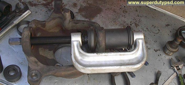
I replaced the ball joints on my four wheel drive 2000 Ford F250 Super Duty. I did the job with the help of Ford factory manuals and several other manuals, as well as other Internet resources. I decided to synthesize what had gleaned from the manuals, and from the practical experience of doing the job into these instructions, which show how to do the job in 47 concise steps. I believe the procedure is the same for model years 1999-2004. The procedure is exactly the same for ball joint replacement on Ford F350 trucks.
Remember though, that I am not a mechanic, this is just how I did it. Before beginning this project, thoroughly read the instructions that came with your replacement ball joints. The various ball joint manufacturers have different requirements, pay particular attention to torque values and the torquing sequence. This write-up is not meant to supplant the vehicle or ball joint manufacturer's recommended procedures for replacing your ball joints.
What does it cost to have the ball joints replaced? It runs from $800.00 on the low side up to about $1500.00 if done by a repair shop or dealer. If you do it yourself it will cost about $300.00.
How long does it take to replace the ball joints? This obviously varies from truck to truck. If you do it yourself, I would plan on 8 hours for the first side and 4-8 hours for the second. You learn a lot on the first side. I hear a lot of do-it-yourselfers claim to do both sides in 2 or 3 hours; I don't believe it. But then, I didn't have this tutorial.
The parts I used are listed below. I went with Moog ball joints because, unlike the Ford OEM ball joints, the Moog's can be greased.
| Required Parts: | |
| Ball Joint, Upper (1 PER SIDE) |
MOOG K80026, FORD F6TZ3V049BA, MOTORCRAFT MCS104273 |
| Ball Joint, Lower (1 PER SIDE) |
MOOG K8607T, FORD 2C3Z3V050BA, MOTORCRAFT MCS104149 |
| Yellow O-Ring, for between hub and knuckle (1 PER SIDE) |
FORD F81Z 4A322AA |
| Axle Seal (knuckle seal), Large outer seal (1 PER SIDE) |
FORD F81Z-3254-CB, SKF 28600 |
| Dust Seal, Small inner seal (1 PER SIDE) |
FORD F81Z-1S175-HCA, NATIONAL 710413 |
Parts That May Be Needed: |
|
| Axle, Needle Bearing, Front (if needed) | FORD C6TZ-3123-A, NAPA B2110 |
| Axle Shaft, Outboard End (if needed) | FORD 4C3Z-3B387-AA |
| Axle, U-Joint, Front (if needed) | FORD F81Z-3249-AA |
| Autolock Hub O ring (part number includes 2 ea.), (if needed) |
FORD 4C3Z-1K106-AA, Dorman 81060 |
| Wheel Bearing/Hub, front, 4 wheel abs, single rear wheels (might be a good time to check the wheel bearing) |
Timken 515020 Wheel Bearing and Hub Assembly |
Tools Required: |
|
| Torque Wrench |
Axle Seal (knuckle seal) Installer (Special Tool) Generic part number OTC 6695 (60-80$) Home Made Version- Axle Seal (knuckle seal) Installer (Special Tool) Purchase OTC 6695 - Ford Axle Shaft Seal Installer |
| Breaker Bar | |
| Ratchet and Extensions | Pickle Fork |
| Sockets 1 5/16", 1 1/8", 21mm, 8mm | Punches and Pry Bars |
| Pullers (some people manage without pullers) | Large Hammer |
| Ball Joint Press (I rented this at Checker for $5) | Snap Ring Pliers (big ones) |
Click here to see the instructions that came with the Moog ball joints in this write-up.
THE WRITE-UP:
Note that I sprayed everything with PB Blaster the night before and it seemed to help.
1) Raise and support the front of the truck according to manufacturer's recommendations using proper jack stands.
2) Remove the front wheels.
3) Remove the rubber ESOF vacuum line from fitting on the knuckle. It just pulls off. It is shown in the photo below.
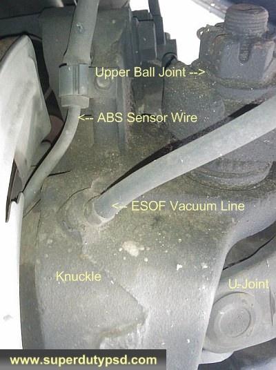
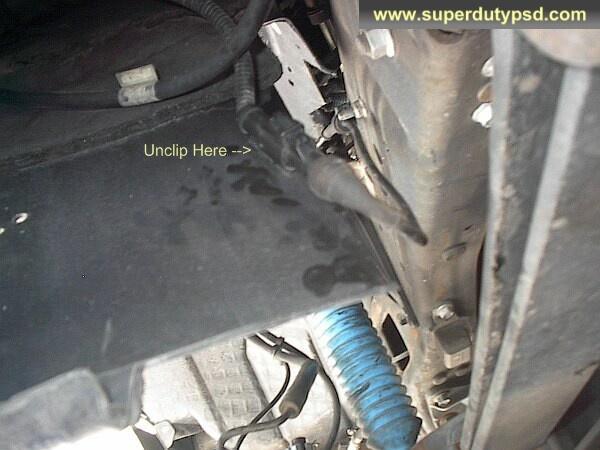
4) Unclip the ABS sensor from the frame and behind the fender well. The ABS sensor does not have to be removed from the bearing. (see photo below)
5) Remove the bolt (8mm socket) that attaches the ABS sensor wire to the knuckle. (see photo below)
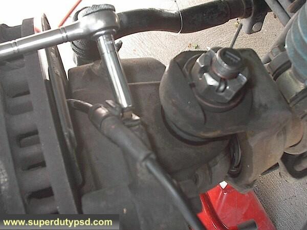
6) Remove the two bolts (21mm socket) that attach the caliper mount to the knuckle. (see photo below)
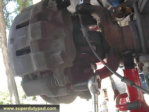
7) Set the caliper mount on top of the front spring and secure it so it does not fall and damage the brake line or your toes. Do not let it hang from the brake line! (see photo below)
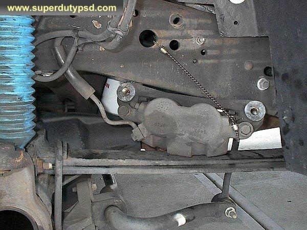
8) Remove the brake rotor. On one side, I had quite a bit of trouble, but it will come off. I ended up tapping on it pretty good with a hammer on a block of wood.
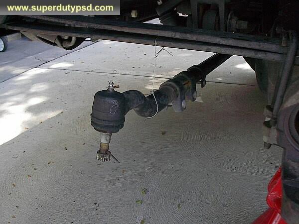
9) To remove the tie rod end, remove the cotter pin from the castellated nut and then the nut (21mm socket) that attaches the tie rod end to the knuckle. (see photo below)
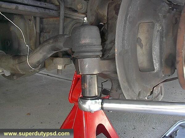
10) I removed the tie rod end using a high quality posi-lock puller that I happened to have. A pitman arm puller can also be used and some have success just tapping it with a hammer. Be careful not to damage the grease boot or the threads. Support the tie rod. (see photos below)
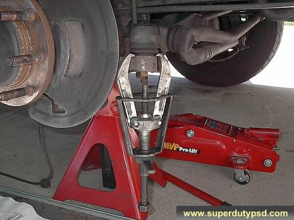
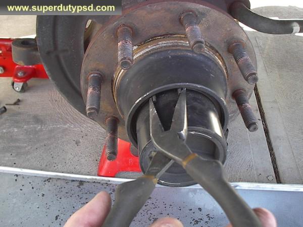
11) Remove the outer hub (this is the auto/manual locking hub). To do this, remove the retaining ring by squeezing the ring together with your fingers or a pair of pliers. You then just pull the assembly out. It can be difficult but keep trying and it will come. While you have the outer hub out, it would be a good time to clean it up and grease the needle bearing that is part of the assembly. (see photo below)
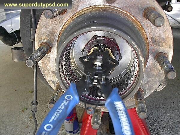
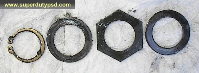
12) Remove the snap ring and thrust washers from the axle where the outer hub assembly was previously. Pay careful attention to the order in which the washers come out, as they need to go back in the same order. They are shown in the proper order in the second photo below. (see photos below)
13) Remove the four nuts (21mm socket) that attach the wheel bearing/hub to the knuckle. (see photo below)
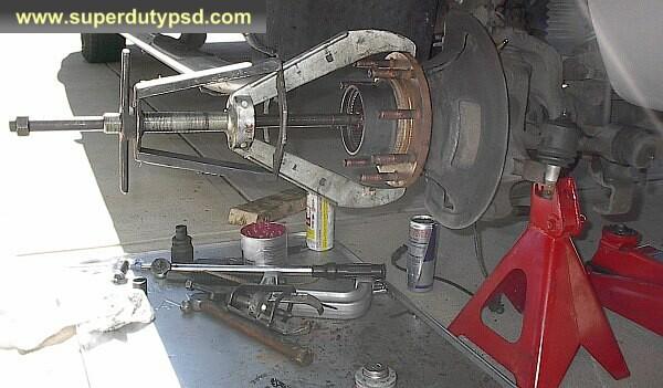
14) Remove the wheel bearing/hub. This can be difficult. On one side, I was able to just tap the assembly with a hammer and then pull on it very hard and it came right out. On the other side, I ended up using another larger posi-lock puller. Don't worry, you likely won't need a big puller like this, I had the puller, so I took the easy way out. I have heard of others that had to use a punch to pound on the wheel bearing/hub studs to get the assembly out of the knuckle. If the studs are in poor shape they may need replaced. (see photo below)
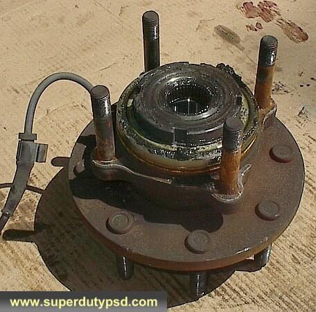
15) With the wheel bearing/hub out, you should check the condition of the needle bearing and the axle it rides on. If the needle bearing is in poor shape it may need replaced and it may have damaged the stub axle. If the axle and bearing are in good shape just clean and re-grease the needle bearing. Just use your finger to press grease into the needle bearing. (see photo below)
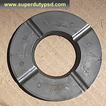
16) Remove the plastic thrust washer from the axle, noting the way it comes out. There are four grooves on the washer and they go toward the axle. (see photo below)
17) Next, remove the axle. Removing the axle shaft is not difficult, with the hub/wheel bearing out, there is nothing but the axle seal (knuckle seal) (F81Z-3254-CB) holding it in place. I used a pry bar to get it started and then just pulled it out. (see photo below)
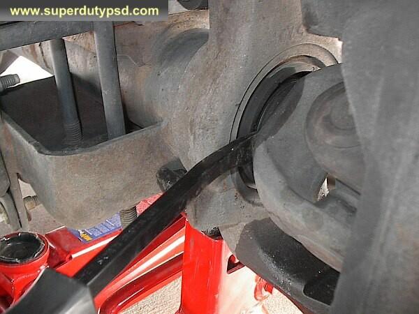
18) With the axle still in the knuckle, the axle seal (knuckle seal) (F81Z-3254-CB) can be pounded off with a punch and hammer, or in my case a small pry bar. (see photos below)
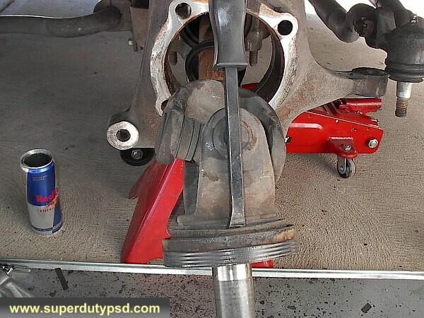
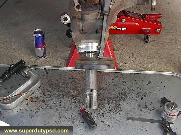
19) With the axle out it is a good chance to check the u-joint (F81Z-3249-AA). If the u-joint (F81Z-3249-AA) is in poor shape it should be replaced. (see photo below)

20) Remove the cotter pin from the upper ball joint castellated nut and loosen both the upper (1 1/8 socket) and lower (1 5/16 socket) nuts. Leave the nuts on a few threads to catch the knuckle when the ball joints break free of the axle.
21) A pickle fork can be used to separate the ball joints from the axle housing. I was uncomfortable doing the top one with a pickle fork because of the camber-adjusting sleeve, so I just beat on the lower one and they both broke free. Be sure not to change the position of the camber-adjusting sleeve. If the camber-adjusting sleeve changes position an alignment may be necessary. It might be wise to mark its position to start with. (see photos below)
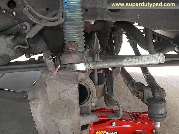
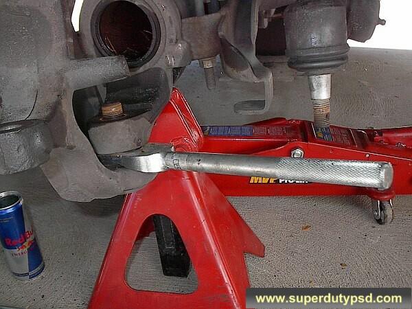
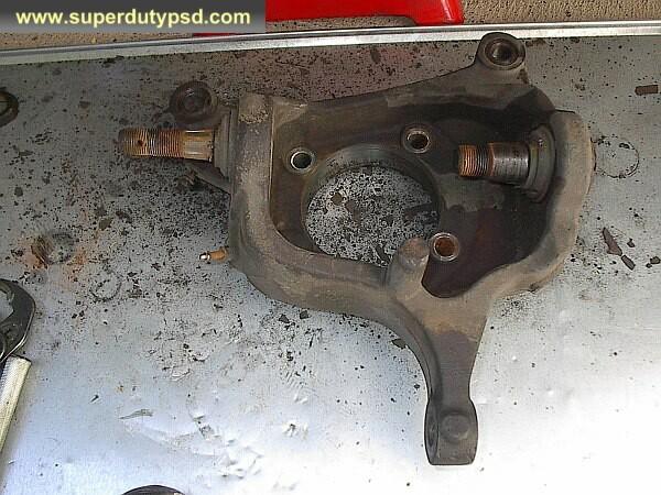
22) Clean the axle tube and the surface where the new dust seal (F81Z-1S175-HCA, NATIONAL 710413) will seat. (see photo below)
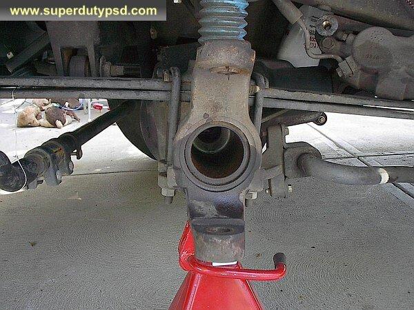
23) Now for the fun part; removing the ball joints from the knuckle. I found it easier to remove the lower ball joint first. First, remove the snap ring, then either beat it out with a hammer or use a ball joint press.
24) To remove the upper ball joint from the knuckle, I used a sledgehammer and a piece of 1.25" pipe with a cap to pound it out. I found this far easier and faster than removing the ball joint with a ball joint press. (see photo below)
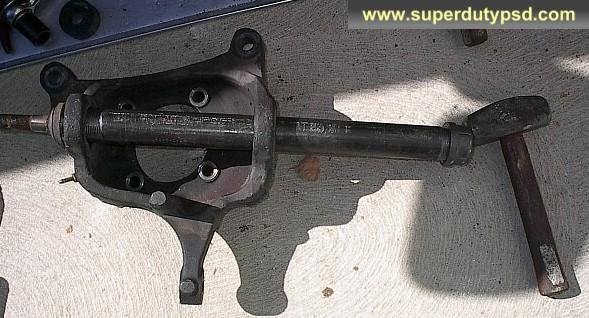
25) Now that the ball joints are out, clean the surface where the new ball joints will seat.
26) Using a ball joint press, press in the new ball joints. (see photo below)

27) Put the snap ring on the new lower ball joint.
28) Position the knuckle with the new ball joints onto the housing again and put the lower ball joint nut on.
29) Torque the lower ball joint nut (1 5/16" socket) TO 35 LB/FT ONLY AT THIS TIME . To keep the ball joint from spinning, you may have to apply light pressure to the knuckle with a floor jack. (see photo below)
- The torque and sequence required may be different depending on the manufacturer of the ball joint, check the documentation that came with the ball joint!
- The value I give here is per the Ford manual for OEM ball joints, which happen to be the same as the Moog joints used for this article.
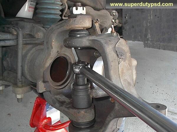
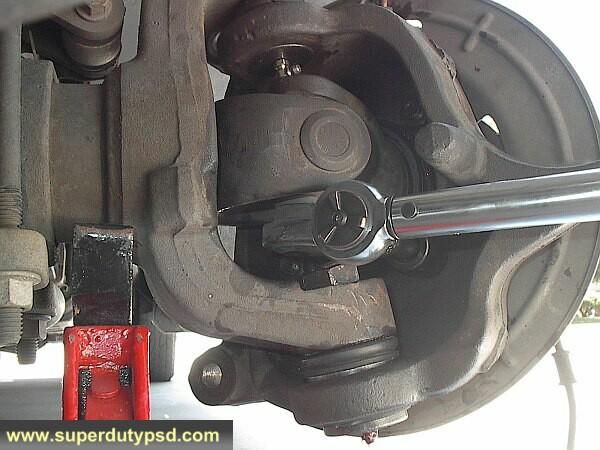
30) Tighten the upper castellated nut (1 5/16" socket) to 69 lb/ft. Insert cotter pin. If the hole does not line up for the cotter pin, tighten the nut a little more, do not loosen to align the hole. (see photo below)
- The torque required may be different depending on the manufacturer of the ball joint, check the documentation that came with the ball joint.
- The value I give here is per the Ford manual and happens to be the same as the ball joints I installed.
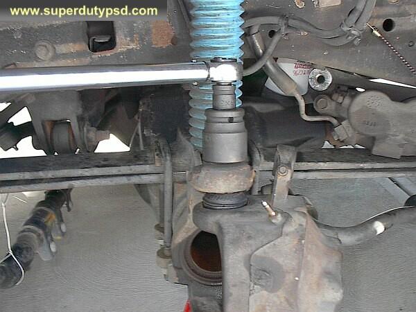
31) Now tighten the lower ball joint nut (1 5/16" socket) to 150 lb/ft. (see photo below)
- The torque required may be different depending on the manufacturer of the ball joint, check the documentation that came with the ball joint.
- The torque value I give here is per the Ford manual. Use the torque value in the instructions that came with your ball joints.

32) At this point, I cleaned the inside of the knuckle with sand cloth and put a film of grease in it.
33) Now to install the axle (F81Z-3254-CB) and dust seals (F81Z-1S175-HCA, NATIONAL 710413). (see photo below)
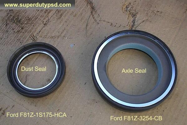
34) To install the larger axle seal (knuckle seal) (F81Z-3254-CB) you will need a special tool. For instructions on building the special tool, click here. Below is a picture of the special tool (the home made version). (see photo below)
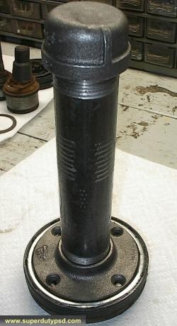
35) Set the axle on some thick cardboard or use a vice and just pound the axle seal (knuckle seal) (F81Z-3254-CB) on until it seats. Don't pound to far/hard or it will distort the seal. When you install the wheel bearing it will fully seat where it needs to be. You will not have this issue if you buy the tool from ford as it will better protect the seal, but it costs hundreds of dollars. You can buy the "special tool" for about 40$-$80 using the part number OTC 6695. The axle and seal can also be taken to the dealer and they will press it on. For me it was easier to make the tool and do it myself. The seal goes on quite easily with the "special tool". (see photo below)
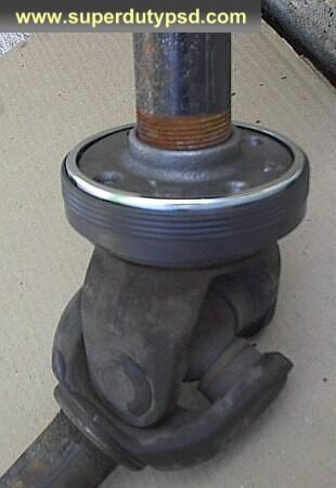
36) Install the dust seal (F81Z-1S175-HCA, NATIONAL 710413) on the axle. It just slips on with no special tools required. (see photo below)
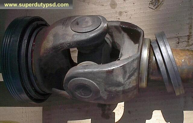
37) Put grease on the outer surface of the axle seal (knuckle seal)(F81Z-3254-CB) and carefully reinstall the axle. It just slides in and when you tighten down the wheel bearing/hub assembly it will properly seat the axle. (see photo below)
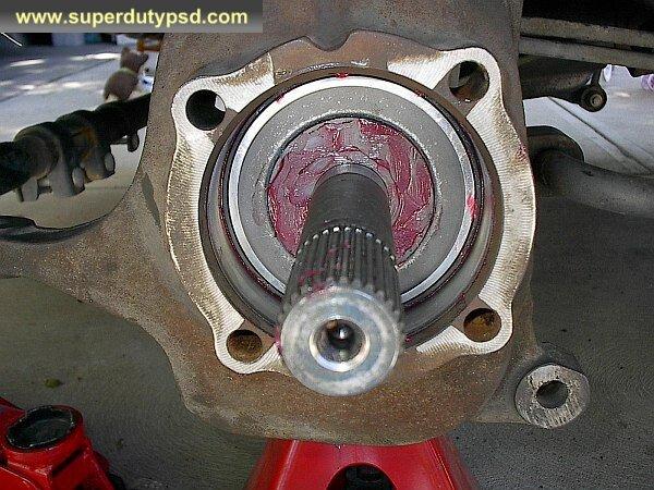
38) Coat the plastic thrust washer with grease and put it back in place with the 4 grooves toward the truck. (see photo below)

39) Now it is time to put the wheel bearing/hub assembly back in place. If you haven't done so already, clean it up and grease the needle bearing. It would also be a good time to clean and/or replace the studs. Do not forget to replace the yellow o-ring. A thin layer of grease will help it seal. (see photo below)
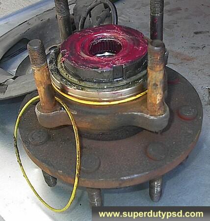
40) Slide the wheel bearing/hub assembly back into the knuckle and cross tighten the four nuts to 133 lb/ft.
41) Grease the outer hub thrust washers and put them back on the axle in the proper order. Proper order is shown in the photo below. Install the snap ring. (see photo below)

42) Check the condition of the outer hub o-ring and replace if necessary. A light coating of grease will help it install and seal. Put the outer hub back in place and put the retaining ring back on.
43) Put the disc brake rotor back on. Put one lug nut on to hold it in place.
44) Install the disc break caliper mount and tighten the two bolts (21mm socket) to 166 lb/ft. (see photo below)
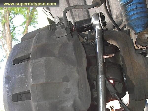
45) Put the ABS sensor and ESOF vacuum line back on. Where the ABS wire attaches to the knuckle tighten the bolt (8mm socket) to 13 lb/ft.
46) Reattach the tie rod end, torque the castellated nut to 52 lb/ft, and put the cotter pin back in place. Again, if the hole does not line up, tighten a little more until it does. Do not loosen the nut to align the hole.
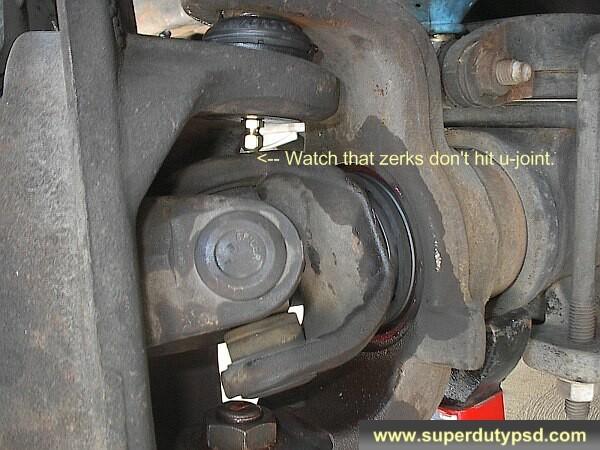
47) Grease the ball joints if they are greaseable! NOTE: If you use greaseable ball joints make sure the zerks do not hit the axle. Determine this by turning the axle by hand one full revolution. If zerks hit the axle you will need to grind them a little. A dremel works great for this, the zerk need not even be removed. (see photo below)
Put the wheels back on. Spin the tire to make sure everything spins okay. Spin the tires with the hubs locked too. This will cause the axles to spin. Check and double check everything. Take it easy when you first try to drive your truck given that the brakes were off. Make sure everything is working. Now you're done and you probably save a bit of money!